Saturday 30 August 2014

Rafters and Ridge Board

Having never done this before it was a case of phoning a builder friend to ask a few questions.

For terminology, have a look at:
http://collections.infocollections.org/ukedu/uk/d/Jgtz006e/14.3.html

 The advice went as follows.

1. In order to work out the location (& depth) of your birds mouth cut, cut over length rafters at the desired roof pitch. In my case the pitch is 45° to maximise head space in the loft.
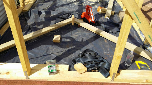
2. Cut a short length of the ridge board and stand it on its end (see left of the orange nail gun).
3. Place the length rafters horizontally on the bottom plate to replicate how they would look when placed on the roof ie along the centre line of the two long walls.
4. Mark the desired overhang of the rafter.
5. Mark the position where the rafters contact the edge of the wall. This is where a "birds mouth" cut will be made. Make the depth of birds mouth cut with consideration to maintaining the structural integrity of the rafter.
6. Cut the birds mouth and reposition back on the ground as per step 3.
7. Measure the distance from the bottom plate to the bottom of the ridge board and write it down.

Before cutting more rafters, the ridge board should be installed to check that the two rafters fit.


To position the ridge board, nail a long length of timber to one side of the centerline of the frame. This structure will be removed later however it needs to be firmly secured.

Position a block of wood at the height of the ridge board as noted in Step 7 above.
The ridge board will rest on this block. Repeat this for the other end of the tiny house.


Position the ridge board on the blocks and clamp. Loose fit the two rafters that were previously cut and make any necessary adjustments in the position of the birds mouth, the angle that the rafter meets the ridge board or the height of the ridge board.

Note that I wanted an eve at both ends of the tiny house so the ridge board is over length.


Cut additional rafters as required. When cutting and fitting rafters, the assumption is that the walls are straight, level, plumb. Note that the rafters will want to spread or push the two long walls apart.
In order to minimize the potential of spreading, the loft bearers were fitted prior to the installation of the rafters.

The long length of timber that can be seen in the photo below is a plant that was worked off when fitting the rafters. Much easier than working off the top of a ladder. 

Construction was during an Australian winter and due to shorter daylight hours the majority of work was undertaken on the weekends. Black builders plastic was placed over the whole structure to stop the chip board floor from getting unnecessarily wet.


Internal view of the rafters. This was the first time that the internal space of the tiny house could be "felt". Note the working plank.


Sunday 10 August 2014

Sub-frame Construction - 3

In these photos you will see that the whole frame has been moved away from circular bulb garden bed where it was originally placed and it has now been moved and placed on levelled concrete blocks.

The area beneath the concrete block was dugout to a depth of 400mm and crushed rocked placed and compacted with the blunt end of a crow bar. In order to stop the double concrete blocks from moving away from each other, they were glued utilising "liquid nails".

Sub-frame has been nogged out with additional floor joist placed at 450mm centers and whole structure is quite rigid.

Love the nail gun.
 

Concrete blocks have been liquid nailed together and are placed on compacted crushed rock.


Sub-frame Construction - 2

Just realized that I neglected to state that the tiny house I am building is designed to be "skid mounted" so that it can be tilt tray moveable and/or retro-fitted for towing.
 
The draw bar and axle arrangement are conceptual and remain in my head. We have friends who have a farm so at worst case the distance to be moved is about 15km away.
 
Now that the sub-frame is parallel, the next challenge is to pull it into "square". This was achieved by the use of ratchet straps and a large plasters square.
Dimensions where still checked by measuring "corner to corner", noting the measurements then measure the opposite "corners to corner".
 
Once square, metal floor joists were welded to the ends of the RHS.
 
In order to ensure that the structure was kept square, diagonal bracing was welded beneath the floor joists.
Parallel RHS prior to welding in the end metal floor joists, one of which can be seen on top of the floor.
50mm x 50mm galvanized RHS welded beneath the floor joists to provide rigidity to the whole structure.
Means of securing the cross bracing.
Some of the floor joists had knots in the timber and appeared weak. In this case the weak section was strengthened by "doubling up" and securing with nails.

Sunday 3 August 2014

Sub-frame Construction

 
The next step was to decide on the dimensions of the floor.

In Australia materials such as flooring come in standard sheet sizes so it worth considering this to minimise waste eg 900mm x 3600mm yellow tongue flooring. Pine comes in a maximum length of 6000mm. Additionally thought has to be given to transport regulations eg maximum width, length and height (4.2m for most loads on trucks).
 
Larger dimensions are possible however permits and restricted routes may apply.

I settled on floor dimension of 2300mm x 4800mm to sneak within truck width constraints and standard material lengths.
 
The RHS beams have been cut to length and leveled using blocks, wood and packers.
In this photos below I have cut the floor joists to achieve the overall width of 2300mm. 
 
Previously I mentioned that the RHS had tabs welded at 600 mm centres. The result of welding the tabs is the bowing of the RHS by approximately 25mm, hence the blue ratchet strap to pull the sides in.


Note the ratchet strap to pull the RHS inward so that they are parallel.


The floor joists were ripped on a Tritton work bench so that they would slip either side of the tabs on the RHS and a bold would supply clamping force.


Floor joist secured to the RHS

 
In order to stop the floor joists from falling below the level of the RHS, short blocks of scrap wood were added. Remember I am essentially undertaking the construction by myself.